What's on this page
- Why rebar is counted on a grid, not by the yard
- The rebar quantity formula in one line
- Bars in one direction: divide the clear span, then add one
- Turning the bar count into linear feet
- Bar sizes and the eighths rule that names them
- Weight per foot, derived rather than looked up
- What grid spacing does to the linear feet
- A worked slab: 20 by 30 feet at 18 inch centres
- Lap splices and the linear feet they quietly add
- Stock lengths, cutting, and the drop you cannot use
- The waste allowance, derived from the cuts
- Cover: the dimension that decides where the grid stops
- Chairs, dobies, and holding the steel at height
- Welded wire mesh versus bar, compared by steel area
- Steel area per foot and the ratio arithmetic
- Footings and thickened edges: counting by the run
- Corner bars, dowels, and the pieces the grid misses
- Slabs with openings, angles, and odd shapes
- Piers, sonotubes, and vertical bar
- Tie wire, and counting the intersections
- Buying rebar: bundles, delivery weight, and handling
- Where a rebar estimate goes wrong
- Your rebar order checklist
- The bottom line
A rebar order is a grid problem wearing the costume of a materials problem. Nothing about the steel is poured or spread, so there is no coverage rate to look up and no bag yield to divide by. What there is instead is a spacing, a slab, and a count that falls straight out of the two: how many bars fit across the width, how many across the length, how long each one is, and how much extra the overlaps eat. Every one of those is arithmetic you can check on paper in a minute.
What makes rebar different from the other quantities on this site is that the arithmetic is completely reliable and the inputs to it are not. The division that turns a slab dimension into a bar count never changes. The spacing you feed it, the cover you set, the bar size, and the splice length are all decided by your local code, your drawings, and whoever engineered the slab. This manual is strict about that line: it shows the maths in full and it refuses to hand you a spacing.
Key takeaways
- Bars in one direction come from one division and one addition: clear span divided by spacing, rounded down, plus one, because a grid has one more bar than it has gaps.
- Linear feet is that count times the bar length, done once for each direction and added, which on the 20 by 30 foot slab used throughout comes to 803 feet before any allowance.
- A grid at spacing s uses roughly 2 divided by s linear feet of bar per square foot of slab, so 18 inch centres run near 133 feet per 100 square feet and 12 inch centres near 200.
- Lap splices, cutting waste, and stock length are separate additions on top of the field count, and they took the worked slab from 803 feet to a 909 foot order of 46 sticks weighing about 607 pounds.
- Spacing, bar size, cover, and splice length are code and design decisions, so run the arithmetic on the numbers your drawings and building department give you rather than on the illustrative ones here.
Why rebar is counted on a grid, not by the yard
Most of the materials on this site fill a volume or cover an area. Gravel takes the shape of the trench, concrete takes the shape of the form, and paint spreads across whatever wall is in front of it, so the estimate is a volume or an area divided by a rate. Reinforcing steel does none of that. It sits in the concrete as a set of discrete straight pieces at a stated interval, and the count depends on where those pieces start and stop rather than on how much space the slab encloses.
That difference has a practical consequence worth stating early. Two slabs of identical area can want wildly different quantities of steel, and it is not because one is bigger. A 600 square foot slab at 12 inch centres wants roughly double the bar of the same slab at 24 inch centres, and a long thin slab wants more than a square one of the same area because the shorter dimension forces more of the long bars in. Area alone cannot tell you the answer.
So the first thing to settle is not the slab size but the grid: the spacing in each direction, the bar size, and how far the outermost bar sits from the edge of the concrete. Those three come off the drawings or out of a conversation with your building department. Once you have them, the slab dimensions finish the job in two divisions. Everything below assumes you have that set of numbers for your specific project rather than a general figure from somewhere else.
The rebar quantity formula in one line
The whole calculation reduces to a single line, run twice. In one direction it reads: bars equals the clear span across the slab divided by the spacing, rounded down, plus one, and linear feet equals that count times the bar length. Run it once for the bars going the long way, once for the bars going the short way, add the two, then add the splice allowance and the waste.
Take the slab this manual returns to: 20 feet by 30 feet, a grid at 18 inch centres both ways, with the outermost bar set 3 inches in from the edge of the concrete. Bars running the 30 foot direction are spaced across the 20 foot width, so the clear span is 20 minus two setbacks of 0.25 feet, which is 19.5 feet. Divide by 1.5 feet of spacing and you get 13 gaps, plus one, so 14 bars. Each is 30 minus 0.5, or 29.5 feet long, which is 413 linear feet.
Bars running the other way are spaced along the 29.5 foot clear length. That gives 19.67 gaps, rounded down to 19, plus one, so 20 bars, each 19.5 feet long, which is 390 linear feet. Add the two and the field total is 803 linear feet. No table was consulted and no coverage rate was assumed. Run your own dimensions through the material coverage estimator as you read, and the companion below recomputes every section on your slab.
Bars in one direction: divide the clear span, then add one
The add one step is where most rebar counts go wrong, so it deserves its own section. A row of bars at a fixed spacing is a fence, not a floor. Between the first bar and the last there are a whole number of gaps, and there is always one more bar than there are gaps. Divide 19.5 feet by 1.5 feet and the honest reading of that 13 is thirteen gaps, which means fourteen bars.
Leave the plus one out and you understate every direction of every grid. On the running slab that is 14 bars becoming 13 and 20 becoming 19, a shortfall of 29.5 plus 19.5 feet, or 49 linear feet out of 803. That is 6 percent, which is enough to eat most of a waste allowance and leave you short at the far edge. On a small pad the error is much worse: a 6 foot wide footing pad at 12 inch centres has 5 gaps and 6 bars, so dropping one is a sixth of the steel.
The rounding direction matters too. When the clear span does not divide evenly, round the gap count down and add one, which places the bars at or inside the stated spacing and leaves a slightly narrower gap at one edge. Rounding up instead would stretch the spacing beyond what the drawing calls for, which is the one direction a spacing is not allowed to move. Where the leftover matters visually or structurally, split it evenly between the two edge gaps rather than dumping it all on one side.
Turning the bar count into linear feet
Counts are what you lay out and linear feet is what you buy, so the conversion has to be exact. Each bar in a direction runs the full clear dimension of the slab in the other direction, meaning the slab length minus the setback at both ends. On the running slab, the 14 long bars are each 29.5 feet and the 20 short bars are each 19.5 feet, giving 413 and 390 linear feet respectively for a field total of 803.
Note the symmetry hiding in there. Both directions use the same two clear dimensions, just swapped: the count in one direction comes from the clear width and the bar length comes from the clear length, and vice versa. That is a useful check, because if you find yourself multiplying a count by the same dimension you divided, you have crossed the directions. Writing the two lines out one above the other on the sketch catches it immediately.
Linear feet is also the unit that everything downstream runs on. Splice allowance is linear feet. Waste is a percentage of linear feet. Weight is linear feet times pounds per foot. Purchase quantity is linear feet divided by the stock length and rounded up. Get the field figure right and the rest of the order is a chain of one line conversions off it, which is exactly the structure our general estimating manual recommends for any material with more than one unit of sale.
Bar sizes and the eighths rule that names them
Rebar in the imperial system is named by a number, and the number is not arbitrary. It is the nominal diameter of the bar in eighths of an inch. A number 3 bar is 3 eighths of an inch across, a number 4 is 4 eighths or a half inch, a number 5 is 5 eighths, and a number 6 is 3 quarters. Knowing that rule means you never need a size chart to convert a callout on a drawing into a dimension you can measure with a caliper.
Everything else about the bar follows from that diameter. The cross sectional area is pi times the diameter squared divided by four, so a half inch bar is 0.196 square inches, a 3 eighths bar is 0.110, a 5 eighths bar is 0.307, and a 3 quarter bar is 0.442. Those areas drive the weight per foot, the steel area per foot of slab, and the splice length, all of which are covered below. The bar is also rolled with ribs, called deformations, whose job is to lock the bar into the concrete so the two act as one material.
Which size your slab wants is a design output rather than an estimating input, and it interacts with the spacing. Going up a size at the same spacing roughly doubles the steel area between a number 3 and a number 5, and going up a size while widening the spacing can leave the steel area almost unchanged while cutting the bar count. Those trades belong to whoever engineered the slab. Your job is to take the size and spacing off the drawing and count accurately against them.
Weight per foot, derived rather than looked up
Weight matters for two reasons: it decides how the steel gets to the site, and it is how rebar is often priced and sold in bulk. It is also completely derivable, which means you never have to trust a number someone typed into a chart. Steel weighs about 490 pounds per cubic foot. A bar one foot long has a volume of its cross sectional area in square inches divided by 144, which converts square inches to square feet, so the weight per foot is that area over 144 times 490.
Run it on the sizes above. A half inch bar has 0.196 square inches, so 0.196 divided by 144 is 0.001363 cubic feet per foot, times 490 gives 0.668 pounds per foot. A 3 eighths bar gives 0.376, a 5 eighths gives 1.04, and a 3 quarter gives 1.50. Those figures agree with the ones commonly published, which is the point of deriving them: the derivation is a cross check on the table rather than a replacement for it, and it survives a mill certificate that lists something slightly different.
Apply it to the running slab. The order works out at 909 linear feet once splices and waste are in, and at 0.668 pounds per foot that is about 607 pounds of number 4 bar. Specify number 5 instead and the same 909 feet becomes about 948 pounds, which is the difference between two people carrying bundles and a delivery that wants a forklift. Weight is the number to work out before you decide how the steel arrives, and it belongs on the order sheet next to the linear feet.
What grid spacing does to the linear feet
Spacing is by far the largest lever on a rebar quantity, and the relationship is simple enough to carry in your head. Ignore the edge effects for a moment and picture one square of the grid, s feet on a side. That square contains one bar length of s along one edge and one along the other, so two linear feet of bar for every s squared square feet of slab. Divide and the rate is 2 divided by s linear feet per square foot.
That single expression predicts the whole spread. At 24 inch centres the rate is 1.0 linear foot per square foot. At 18 inches it is 1.33, at 16 inches 1.5, at 12 inches 2.0, and at 8 inches 3.0. Halving the spacing doubles the steel, which is why a drawing that says 12 inch centres and one that says 24 inch centres describe orders that differ by a factor of two on the same slab.
Linear feet of bar per 100 square feet of slab, by grid spacing
Each figure is 2 divided by the spacing in feet, times 100. Illustrative spacings for comparison only; the spacing your slab needs comes from your drawings and your building department.
Every value is 200 divided by the spacing in feet, and every bar width is that value divided by the largest, 300, times 100. The running slab lands at 803 feet over 600 square feet, or 134 per 100 square feet, slightly above the 133 the rate predicts because of the extra bar in each direction.
Two cautions about using the rate. It is an approximation that ignores the plus one bar and the edge setback, so it always sits a little below the exact count on a real slab, and the smaller the slab the bigger the gap. Use it to sanity check an order or to compare two spacings quickly, then do the exact count for the number you actually buy. And if the drawing specifies different spacings in the two directions, which is common in one way slabs, work each direction separately rather than averaging.
A worked slab: 20 by 30 feet at 18 inch centres
Here is the whole calculation in one place, in the order you would write it on a sheet. The slab is 20 feet by 30 feet, 600 square feet, with a grid of half inch bar at 18 inch centres both ways and the outermost bar 3 inches in from the concrete edge. Stock bar comes in 20 foot lengths and the splice allowance uses an illustrative 40 diameters.
Step one, the clear dimensions: 20 minus 0.5 is 19.5 feet, and 30 minus 0.5 is 29.5 feet. Step two, the long way bars: 19.5 divided by 1.5 is 13 gaps, plus one is 14 bars, each 29.5 feet, so 413 linear feet. Step three, the short way bars: 29.5 divided by 1.5 is 19.67, rounded down to 19 gaps, plus one is 20 bars, each 19.5 feet, so 390 linear feet. Step four, the field total: 413 plus 390 is 803 linear feet.
Step five, the splices: the 29.5 foot bars exceed the 20 foot stock, so each needs one splice, 14 in total, and at 40 diameters for a half inch bar that is 20 inches or 1.67 feet each, adding 23 linear feet. The 19.5 foot bars fit a stick, so they need none. Step six, the allowance: 803 plus 23 is 826 feet, and 10 percent for cutting and handling takes it to 909 feet. Step seven, the purchase: 909 divided by 20 is 45.5, so 46 sticks, weighing about 607 pounds. The companion returns exactly these figures on these inputs.
Lap splices and the linear feet they quietly add
A splice is where two bars overlap so that force carries from one into the other through the concrete around them. Because the transfer happens by bond along the ribs, the required overlap is written as a multiple of the bar diameter rather than as an inch figure, and that multiple depends on concrete strength, bar size, coating, the cover and spacing around the bar, and whether the bar is in tension. It is genuinely a per project number, so take it from your drawings or your building department and do not lift it from an estimating manual, including this one.
What an estimating manual can do is show you how the number lands in the order. Every splice adds one lap length of bar that does no new work, so total linear feet equals field feet plus the number of splices times the lap. Using an illustrative 40 diameters, a half inch bar wants a 20 inch lap and a 5 eighths bar wants 25 inches. On the running slab that is 14 splices at 1.67 feet, or 23 feet, which is 2.9 percent of the field count.
The share grows fast on longer runs. A 60 foot bar line out of 20 foot stock needs three sticks and two splices, so the lap allowance is two laps per line rather than one, and on a slab with many long runs the splice allowance can pass 5 percent. It also grows with bar size, because the lap scales with diameter while the field feet do not. Run the arithmetic rather than folding splices into a vague waste number, because splices are predictable and waste is not.
Stock lengths, cutting, and the drop you cannot use
Rebar is sold in stock lengths, and the length you buy interacts with the length you need in ways that decide how much steel ends up in the offcut pile. Common stock lengths sit at 10, 20, and longer, with 20 feet the usual default for small jobs and longer sticks available on order from a supplier or a rebar fabricator. Ask what your yard actually stocks before you plan the cutting, because the answer changes the arithmetic.
The interaction is easiest to see on the running slab. The 20 short bars need 19.5 feet each, which comes out of a 20 foot stick with a 6 inch drop that is useless for anything except a dowel or a stake. That is 20 sticks with 10 feet of scrap in total. The 14 long bars need 29.5 feet each, which is one full stick plus 9.5 feet plus a lap, so two sticks per bar with about 9 feet left over each time. Those offcuts are long enough to be worth keeping, and a bit of planning turns two of them into one short bar.
The habit that saves the most steel is cutting from a list rather than from the pile. Write out every piece length the job needs, sort them longest first, and assign them to sticks the way you would fill boxes, fitting the longest remaining piece that will still go in. That is the same discipline our board foot manual applies to lumber cut lists, and it routinely saves a stick or two on a job with mixed lengths.

The waste allowance, derived from the cuts
A flat 10 percent is the figure people reach for, and it is a reasonable working allowance, but it is worth understanding what it is covering so you can move it when the job warrants. On rebar, the allowance has three distinct parts: unusable drops from cutting, bars damaged or bent wrong during handling, and the rounding up to whole sticks that happens at the end anyway.
Cutting drop is the part you can actually compute. On the running slab, the short bars leave 6 inches each from 20 sticks, which is 10 feet, and the long bars leave about 9 feet each after the second stick is cut, though most of that is reusable if the job has anywhere to put it. Damage is smaller on steel than on masonry, since a bar that gets stepped on is still a bar, but bars bent for corners or hooks get miscut, and a badly nicked bar gets set aside.
What the 909 foot rebar order is actually made of
The running example: a 20 by 30 foot slab, half inch bar at 18 inch centres both ways, 3 inch edge setback, 20 foot stock, illustrative 40 diameter laps.
The four segments are 413, 390, 23, and 83 feet against a 909 foot order, so the widths are those figures divided by 909 and rounded to whole percents that sum to 100. Only the first two come from the slab itself; the third comes from the stock length and the fourth from the cutting.
The honest way to set the allowance is to compute the drop from your cut list and then add a handling margin on top, rather than picking a percentage first. On a simple rectangular slab where most bars fit a stick, a smaller allowance is defensible. On a slab full of returns, angles, and openings, where nearly every bar is a custom length, the drop can climb well past 10 percent and the allowance should follow it.
Cover: the dimension that decides where the grid stops
Cover is the thickness of concrete between the steel and the outside world, and it is the reason the outermost bar sits in from the edge rather than at it. Its purpose is durability rather than strength: concrete protects steel from moisture and from the chlorides that cause corrosion, and a bar too close to a surface rusts, expands, and spalls the concrete off in sheets. That is a slow failure but a terminal one.
The required cover is code territory and it varies with exposure. Concrete cast directly against earth is treated differently from concrete formed against a mould, which is treated differently again from an interior surface, and the figures are set by the code your jurisdiction has adopted rather than by convention. This manual will not name a cover figure for your slab, and any calculator that assumes one without telling you is hiding a decision. Get it from the drawings or the building department.
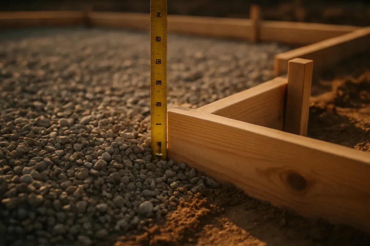
Cover shows up in the count as the edge setback, and it is not the same number. Side cover measures from the vertical edge of the slab to the outside of the bar, so the setback you subtract is the cover plus a small bit for the bar itself if you are being precise. The running slab uses 3 inches purely as a stated illustrative figure, and swapping it changes the counts: at a 2 inch setback the 20 foot direction gives a clear span of 19.67 feet, which still yields 14 bars, while a wider setback on a smaller pad can drop a bar entirely.
Chairs, dobies, and holding the steel at height
Steel that ends up on the ground is doing nothing useful, which makes the supports under the grid part of the material order rather than an afterthought. Reinforcement works by taking tension that the concrete cannot, and it only takes tension if it sits where the tension is. A bar lying on the gravel at the bottom of a slab is in the wrong place for most of the things a slab on grade is asked to do, and it has essentially no cover underneath it.
The hardware comes in a few forms. Plastic or wire chairs clip under the bar at a set height. Concrete blocks, often called dobies, sit under the bar and become part of the pour. Continuous bar supports run under a whole line. Whichever you use, the count is a spacing problem just like the grid: supports every so many feet along every bar, or at every second or third intersection, with the interval chosen so the bar does not sag between them under a boot.
On the running slab, a support at every second grid intersection would be roughly half of 14 times 20, or 140 pieces. That is a real line item and it is the one most first estimates leave out. The related failure is pulling mesh or bar up during the pour with a hook, which sounds efficient and rarely puts the steel at a consistent height. Our slab pouring manual treats support and position as part of the placement sequence, because the grid you counted only counts if it stays where you put it.
Welded wire mesh versus bar, compared by steel area
Mesh and bar get discussed as if they were two brands of the same thing, and the only honest way to compare them is by steel area per foot of slab width. That puts both on one scale and makes the comparison arithmetic rather than opinion. Welded wire fabric is designated by its wire spacing and wire size, where the W number is the wire’s cross sectional area in hundredths of a square inch: a W1.4 wire is 0.014 square inches.
Run the comparison. A light fabric with W1.4 wires at 6 inch centres puts one 0.014 square inch wire into every half foot of width, which is 0.028 square inches per foot. A half inch bar at 18 inch centres puts 0.196 square inches into every 1.5 feet, which is 0.131 square inches per foot. The bar grid carries about 4.7 times the steel area of that fabric. Heavier fabrics close the gap, and the same arithmetic on a heavier wire at a wider spacing lands wherever it lands, which is the point: compute it rather than assuming.
There is a second, more practical difference. Sheet mesh lies flat and stays where it is put. Rolled mesh remembers the roll and fights you, and both are far harder to hold at a consistent height under a boot than a tied bar grid on chairs. A great deal of mesh ends up at the bottom of the slab, where its steel area is beside the point. That placement reality, more than the area comparison, is why bar is common where the reinforcement genuinely matters, and why our manual on why concrete cracks treats reinforcement position as a control question rather than a quantity one.
Steel area per foot and the ratio arithmetic
One more piece of arithmetic is worth knowing, because it is the language drawings and engineers use. The steel ratio is the cross sectional area of steel divided by the gross cross sectional area of the concrete, both taken per foot of slab width. It is how a specification says how much reinforcement a slab has without naming a bar size and a spacing, which lets several combinations satisfy the same requirement.
Compute it on the running slab. A half inch bar at 18 inch centres gives 0.131 square inches of steel per foot of width. A 4 inch thick slab has a gross area of 4 times 12, or 48 square inches per foot. Divide and the ratio is 0.0027, or 0.27 percent. Thicken the slab to 6 inches without changing the grid and the gross area becomes 72 square inches, so the same steel is now 0.18 percent, which is the arithmetic reason thicker slabs often carry tighter grids or larger bar.
What the required minimum ratio is for your slab is a code question, and it differs for shrinkage and temperature steel, for structural reinforcement, and for slabs in different exposure and seismic categories. Do not take a percentage off a forum post. What the ratio arithmetic does give you is a way to check that a substitution keeps the same steel: if a supplier is out of one size, compute the area per foot of the alternative before you accept it, and take the substitution to whoever specified the original.
Footings and thickened edges: counting by the run
Footings count differently from slabs, and the difference is that a footing is a line rather than a field. Continuous bars run along the length of the footing, usually a stated number of them side by side, and the count is not a division at all. It is simply the number of rows times the total run in feet.
Work the perimeter footing under the running slab. A 20 by 30 foot slab has a 100 foot perimeter, so a footing with two continuous bars is 2 times 100, or 200 linear feet, before anything else. The splices are the interesting part: with 20 foot stock, each 100 foot loop takes five sticks and closes on itself, which means five laps per row and ten in total. At the illustrative 1.67 foot lap, that is 17 feet, taking the subtotal to 217 and, with 10 percent, to 239 linear feet or 12 sticks weighing about 160 pounds.
Add that to the slab grid and the whole project reads 909 plus 239, or about 1,148 linear feet of half inch bar weighing roughly 770 pounds. That is the figure that decides delivery. Thickened edge slabs, sometimes called monolithic or turned down slabs, are the same arithmetic with the footing bars sitting in the deepened perimeter of the same pour, which changes the concrete volume rather than the steel count. Our slab concrete manual handles that volume side, and the same 600 square feet at 4 inches is about 7.4 cubic yards before any thickened edge.
Corner bars, dowels, and the pieces the grid misses
Straight bars in two directions do not make a complete reinforcement order, and the pieces that get missed are almost always the bent ones. Corner bars, sometimes called L bars, wrap the corner of a footing so that the two straight runs are tied into each other rather than simply passing. Each has two legs, each leg long enough to lap the straight bar it meets, so a corner bar is roughly two lap lengths plus the bend.
Count them the way you count anything else: rows times corners. The running perimeter footing has four corners and two rows, so eight corner bars. At an illustrative leg length of 3 feet each, that is about 48 linear feet of extra bar, plus the bending, which is either a job for a hand bender on site or a fabrication line item if you are ordering cut and bent steel.
Dowels are the other common omission. These are short bars that tie one pour to the next: slab to footing, footing to wall, old slab to new. They are counted by spacing along a joint, exactly like a grid line, and each has a length that includes its embedment into both pours. Whether your job needs them, at what spacing, and how far they embed is a design and code question, and the answer changes with what the joint has to do. List them on the sketch as a separate item so they get priced, because a bundle of dowels is cheap and discovering you need them the morning of a pour is not. The footing and post manual covers the related case of steel embedded into a small isolated pour.
Slabs with openings, angles, and odd shapes
Real slabs are rarely clean rectangles, and the way to handle a complicated one is the way you handle any complicated area: break it into shapes you can count, count each, and add. Decompose the plan into rectangles first, since a rectangle is where the divide and add one method works directly, then handle the leftovers.
Openings are the easy case and they behave differently from the way they do in a masonry count. A void in a slab, for a floor drain, a column, or a stair, removes some length from a few bars rather than removing area from the whole grid. Compute the field count as though the slab were solid, then shorten the bars that cross the opening, and add back the trim bars the drawing calls for around it, which are usually diagonal or perimeter pieces placed to control the cracking that reentrant corners cause. The net effect on the order is often close to zero, so the safe assumption is that an opening does not reduce your steel.
Angled and curved edges are the harder case. A grid crossing a diagonal edge produces a run of bars that each stop at a different length, and the honest way to count them is to draw the grid on the plan and scale each bar off it. That is tedious but it is the only method that does not either overbuy badly or leave you short at the point. A quick approximation is to treat the shape as its bounding rectangle for the count and then subtract the average shortfall, but check it against the drawing. The same decomposition logic our square footage manual uses for irregular footprints is the right starting point.
Piers, sonotubes, and vertical bar
Vertical reinforcement in a pier or a column is counted per pier, and it has two parts: the vertical bars and whatever ties or spirals wrap them. The vertical count comes off the drawing rather than from a spacing, since a small round pier commonly carries a handful of bars arranged in a circle inside the cover, and the number is chosen by the designer.
The length arithmetic is straightforward. Each vertical bar runs the depth of the pier minus the cover at the bottom and the top, which for an illustrative 4 foot deep pier with a few inches of cover at each end lands near 3.5 feet. Four bars per pier is then 14 linear feet, plus any projection above the pour for dowelling into what sits on top, which can add more than the pier itself if a column or a post base is being tied in.
Ties are counted by spacing along the vertical, exactly like a grid line: pier height divided by the tie spacing, plus one. The length of each tie is the perimeter of the tie shape plus the hooks. This is another place where the practical advice is to price bent steel from a fabricator rather than bending on site once the count passes a couple of dozen pieces, because hand bending consistent ties is slow and inconsistent ties are worse than fewer good ones. Whether your piers need reinforcement at all, and how much, is set by the load and the code, not by the estimate.
Tie wire, and counting the intersections
The grid is held together with tie wire twisted at intersections, and that wire is a consumable the order should include. Counting it is a multiplication: intersections equal the bar count in one direction times the bar count in the other. On the running slab that is 14 times 20, or 280 intersections.
Not every intersection needs a tie. Common practice ties every intersection around the perimeter and at every second or third one in the field, which keeps the mat rigid enough to walk without spending an afternoon on it. Take half the intersections as an illustrative working figure and the running slab wants about 140 ties. Each tie consumes a length of wire, and 8 to 10 inches is a reasonable planning figure for a hand twisted tie including the twist, so 140 ties at 9 inches is roughly 105 feet of wire.
Buy generously, because tie wire is cheap and running out mid mat is annoying, and the coils are sold in weights that will cover a slab this size many times over. The tool matters more than the quantity: a proper twister turns each tie into a two second job, while pliers turn the same job into an afternoon and a sore wrist. Count the ties anyway, because the number tells you how long the placement will take, which is usually the more useful output.
Buying rebar: bundles, delivery weight, and handling
Rebar is sold by the stick at a yard and by the bundle or the ton from a supplier, and the crossover point is worth knowing before you order. A small job of a few dozen sticks is a counter transaction. A job in the tons is a delivery, and it may be cheaper as cut and bent steel from a fabricator, which arrives labelled to a bar schedule and saves you the cutting entirely.
Weight is the practical constraint. The running slab plus its footing is roughly 1,148 linear feet of half inch bar at 0.668 pounds per foot, or about 770 pounds. That is well past what a passenger vehicle should carry and it is 46 plus 12 sticks of awkward 20 foot steel, so it is a delivery or a trailer either way. Twenty foot bar also does not fit in most pickup beds without overhang, which is a real constraint on how you get it to a site.
Two ordering habits pay off. Order by the bar schedule rather than by the total, listing how many pieces of what length you need in each mark, because that is what a fabricator prices and what stops you cutting the wrong pieces first. And confirm the grade and any coating against the drawing, since epoxy coated and galvanised bar exist for corrosion exposure, cost more, and often carry different splice requirements. Our cost manual for concrete covers the pricing side of the pour itself, and the steel is a separate line that belongs beside it.
Where a rebar estimate goes wrong
A handful of errors cover nearly every wrong rebar order, and none of them is difficult arithmetic. They are bookkeeping slips.
- Forgetting the plus one. A grid has one more bar than it has gaps in each direction. Dropping it cost the running slab 49 linear feet, about 6 percent, and costs a small pad far more.
- Counting only one direction. A two way grid needs both counts added. Half an order arrives, which is a mistake that only shows up on the day.
- Ignoring the lap splices. Every overlap adds bar that does no new work. Fourteen splices added 23 feet to the running slab, and long runs out of short stock add far more.
- Multiplying the count by the wrong dimension. The count comes from one clear dimension and the bar length from the other. Crossing them produces a plausible looking number that is wrong.
- Assuming a spacing or a cover. These are code and design outputs. Run the arithmetic on the figures from your drawings, and confirm them with your building department before ordering.
- Leaving out chairs, ties, dowels, and corner bars. The straight grid is most of the steel and none of the accessories. Each is a separate count and each is cheap to include and expensive to discover late.
The sketch prevents almost all of these. Draw the slab, write both clear dimensions on it, mark the spacing in each direction, note the setback, and write the two count lines one above the other. Then the order comes off the drawing rather than out of memory, and it can be checked by someone else in a minute.
Your rebar order checklist
Run down this list before the order goes in. It is the save this asset of the whole calculation.
- Got the bar size, both spacings, the cover, and the required lap from your drawings or your building department, and written them on the sketch.
- Measured the slab inside the forms and subtracted the edge setback from both dimensions for the clear span and the clear length.
- Divided each clear dimension by the spacing, rounded down, and added one, in both directions.
- Multiplied each count by the opposite clear dimension and added the two for the field linear feet.
- Checked the total against the rate: about 2 divided by the spacing in feet, per square foot, which should sit just below your exact figure.
- Counted the splices from the stock length and added one lap length of bar for each.
- Built a cut list of piece lengths, longest first, and set the waste allowance from the drop it produces rather than from a habit.
- Divided the total by the stock length and rounded up to whole sticks.
- Multiplied the total by the weight per foot to get the delivery weight, and planned the transport around it.
- Added the footing runs by rows times perimeter, plus their splices and corner bars.
- Added the chairs or dobies, the tie wire, and any dowels as separate line items.
- Confirmed the grade and coating against the drawing, and confirmed whether an inspection is required before the pour.
Work top to bottom and the order you hand the yard is one you can defend line by line, with the steel priced alongside the concrete rather than remembered on the morning of the pour. The companion runs the same sequence on your own slab, and the material coverage estimator handles the volume side of the same job.
The bottom line
A rebar count is one division and one addition, done twice. Subtract the edge setback from each slab dimension, divide the clear span by the spacing, round down, add one, and multiply by the opposite clear dimension, once for each direction. Add the two, add a lap length for every splice the stock length forces, add a cutting allowance built from the cut list, and round up to whole sticks. On the slab carried through this manual, that sequence gives 14 bars one way and 20 the other, 803 field feet, 909 feet to buy, 46 sticks, and about 607 pounds of steel, with the perimeter footing adding roughly 239 feet more. Every one of those numbers rests on a spacing, a cover, and a splice length that came from somewhere else, which is the honest division of labour here: the arithmetic is yours to run, and the requirements are your building department’s and your engineer’s to set. Run your slab through the material coverage estimator, check the total against the rate, and get the reinforcement design confirmed before a single bar is cut.
Read this as bench notes on the counting, not as a reinforcement specification. The spacings, bar sizes, edge setbacks, lap lengths, tie intervals, support intervals, stock lengths, and waste percentages used here are stated illustrative assumptions chosen to make the arithmetic legible, and the real values for your project are set by the code adopted where you build, by the loads the concrete will carry, by the soil beneath it, and by whoever engineered the slab. Nothing here specifies slab thickness, reinforcement, cover, splice length, footing depth, dowelling, or whether a slab needs steel at all. Confirm stock lengths, grades, coatings, and weights with your supplier, and take the reinforcement design and the inspection requirements to your local building department and a qualified professional before you order, cut, or place any bar.
Frequently asked questions
How do I calculate how much rebar I need for a slab?
Work one direction at a time. Subtract twice your edge setback from the slab dimension the bars cross, divide that clear distance by the spacing, round down, and add one, because a grid of bars has one more bar than it has gaps. Multiply that count by the length of a single bar, which is the other slab dimension minus twice the setback. Repeat for the second direction and add the two totals for the field linear feet. On a 20 by 30 foot slab at 18 inch centres with a 3 inch setback, that is 14 bars at 29.5 feet plus 20 bars at 19.5 feet, or 803 linear feet before splices and waste.
How much rebar is in 1,000 square feet of slab?
It depends almost entirely on the spacing, and the rate is easy to derive rather than look up. A grid at spacing s feet uses roughly two linear feet of bar for every s square feet of slab, so the rate approaches 2 divided by s linear feet per square foot. At 18 inch centres that is about 1.33 linear feet per square foot, or roughly 1,330 linear feet per 1,000 square feet. At 12 inch centres it is about 2,000, at 16 inch centres about 1,500, and at 24 inch centres about 1,000. Small slabs run slightly above those rates because of the extra bar in each direction.
What spacing should rebar be at in a concrete slab?
That is a design decision rather than an estimating one, and it is not something a quantity manual can answer for your project. Spacing, bar size, slab thickness, cover, and whether the slab needs reinforcement at all are set by your local building code, by the loads the slab will carry, and by the soil under it, and a residential patio, a garage floor, and a structural slab can land in very different places. Common residential drawings often show a grid somewhere between 12 and 24 inches on centre, but treat any figure you see quoted as a starting point for the arithmetic and confirm the real one with your building department or the engineer on the job.
How long does a rebar lap splice need to be?
Long enough for the bond between steel and concrete to develop the bar's strength, which is why the requirement is written as a multiple of the bar diameter rather than as a fixed inch figure. The multiple depends on concrete strength, bar size, bar coating, the spacing and cover around the bar, whether the bar is in tension, and which code your jurisdiction has adopted, so it genuinely varies from job to job. This manual uses an illustrative 40 diameters purely to show how splice length feeds into linear feet, which is 20 inches for a half inch bar, and every splice figure in it is an example rather than a specification. Get the number for your project from the drawings, the engineer, or the building department.
How much does rebar weigh per foot?
You can derive it instead of trusting a table. Steel weighs about 490 pounds per cubic foot, so the weight per linear foot is the bar's cross sectional area in square inches divided by 144, times 490. A half inch bar has an area of 0.196 square inches, which gives 0.668 pounds per foot. The same arithmetic gives roughly 0.376 pounds per foot for a 3 eighths inch bar, 1.04 for a 5 eighths inch bar, and 1.50 for a 3 quarter inch bar. Multiply by your total linear feet to get delivery weight, which is what decides whether the order comes in a truck or in the back of a pickup.
Is wire mesh as good as rebar in a slab?
They are not interchangeable by name, only comparable by steel area, and that comparison usually favours bar by a wide margin. Compare them per foot of slab width. A half inch bar at 18 inch centres puts 0.196 square inches of steel into every 1.5 feet, which is about 0.131 square inches per foot. A light welded wire fabric with 0.014 square inch wires at 6 inch centres puts about 0.028 square inches per foot, roughly a fifth as much. Mesh is also far harder to hold at the right height during a pour, which is the failure that leaves steel sitting on the ground doing nothing. Which one your slab needs is a code and design question.
How many bars do I need if the slab is 20 feet across at 18 inch spacing?
Divide and add one. With a 3 inch setback at each edge, the clear distance is 19.5 feet, and 19.5 divided by 1.5 feet is 13 gaps, so the answer is 14 bars. The add one step is the part people miss: a run of bars has one more bar than it has spaces between bars, the same way a fence has one more post than it has sections. Dropping that bar understates a large grid by a few percent and understates a small one badly, and it is the single most common error in a rebar count.
Do I need a permit or an engineer to put rebar in a slab?
Very possibly, and the reinforcement is exactly the part a building department cares about. Slab thickness, bar size, spacing, cover, splice lengths, footing depth, dowel requirements, and whether an inspection is needed before the pour are all set locally, and they change with frost depth, soil conditions, loads, and seismic and wind exposure. Anything carrying a structure, retaining soil, or supporting a vehicle deserves a real design rather than a rule of thumb off the internet. Use the arithmetic here to price and plan the steel, then confirm every dimension against your permit set, your building department, and a qualified professional before the bar is cut.